This paper adds a bit more details to how a Sigma-Delta ADC works.
For a general ADC paper refer to A/D converters.
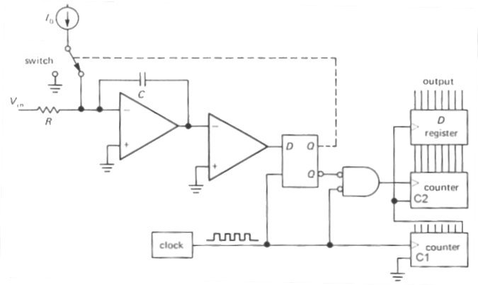
In the schematic above the input analog voltage drives an integrator, whose output is compared with a ground
voltage level by a comparator. D-latch controls the switch turning on/off reference voltage,
they both are composing a 1-bit DAC.
As the input voltage increases or decreases, the comparator turns on and off the reference voltage,
that is subtracted from the input signal, aiming to maintain zero on the output of the integrator.
The counter C1 keeps track of clock periods, while counter C2 counts the number of pulses when the switch is closed.
Suppose the volume of counter C1 is 1000. By the time it gets the final count, the number in counter C2
is proportional to the average level of the input signal during the time of 1000 clock pulses.
Now the name delta-sigma is making a little more sense: delta (the difference) refers to delta modulation,
the principle of coding not the whole input value, but only the difference between the current signal sample
and the feedback signal, corresponding to the previous sample. Obviously, less bits are required to code only the difference
in the amplitudes.
Sigma (the sum) is because the sum of "deltas" is counted during the measured interval. In other words,
the input to the quantizer is the integral of the differences between the input and the output signals.
Technical papers often refer to sigma-delta converter as over-sampling. Traditional converter takes a sample of
the input signal and performs a complete conversion with it. Delta-sigma converter is averaging multiple samples.
The penalty paid for the high resolution achievable with sigma-delta technology has always been speed - the hardware has to operate at the
oversampled rate, much larger than the maximum signal bandwidth, thus demanding greater complexity of the digital circuitry. Because of
this limitation, these converters have traditionally been used in high-resolution low frequency applications (up to 1 MHz,
such as speech, audio, precise voltage and temperature measurements).
References:
- J. Candy and G. Temes, "Oversampling methods for A/D and D/A conversion," in Oversampling Delta-Sigma Data Converters,
pp.1-25, IEEE Press, 1992.
- P.M. Aziz, H.V. Sorensen and J. Van Der Spiegel, "An overview of sigma-delta converters," IEEE Signal Processing Magazine, Vol.13
|
|
|
|
|
Do you know how much you are worth on the market?
If you stayed with the same company
for a lengthy period of time, there is a big chance you are under-earning.
More... |
|
|
|
|