Direct-conversion ADCs
Direct conversion is also known as a flash conversion. ADCs based on this architecture are extremely fast with a sampling rate of upto 1GHz .
However, their resolution is limited because of the large number of comparators and reference voltages required.
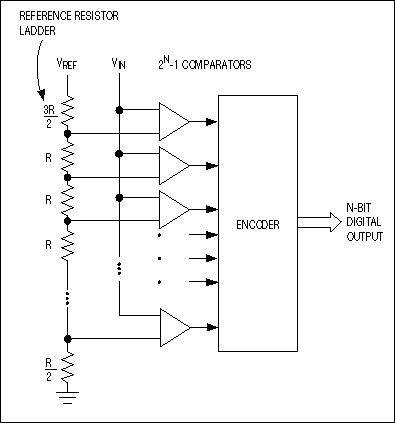
The input signal is fed simultaneously to all comparators. A priority encoder generates a digital output
that corresponds with the highest activated comparator.
The identity of comparators is important, any mismatch can cause a static error.
Flash ADCs have a short aperture interval - the time when the comparators' outputs are latched.
Successive-approximation ADCs
The conversion technique based on a successive-approximation register (SAR), also known as bit-weighing conversion, employs a comparator to weigh the applied input voltage against the output of an N-bit digital-to-analog converter (DAC). Using the DAC output as a reference, this process approaches the final result as a sum of N weighting steps, in which each step is a single-bit conversion.
Initially all bits of SAR are set to 0. Then, beginning with the most significant bit, each bit is set to 1 sequentially.
If the DAC output does not exceed the input signal voltage, the bit is left as a 1. Otherwise it is set back to 0.
It is kind of a binary search. For an n-bit ADC, n steps are required.
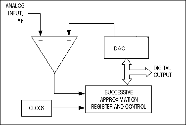
SAR converters sample at rates to 1Msps, draw low supply current, and offer the lowest production cost.
Integrating ADCs
A classical dual-slope converter is shown at the drawing.
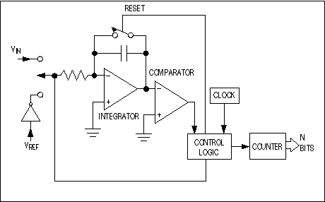
A current, proportional to the input voltage, charges a capacitor for a fixed time interval Tcharge.
At the end of this interval the device resets its counter and applies an opposite-polarity (negative) reference
voltage to the integrator input. With this opposite-polarity signal applied
the cap is discharged by a constant current until the voltage at the output of the integrator reaches zero again. The time Tdischarge
is proportional to the input voltage level and used to enable a counter. The final count provides the digital output,
corresponding to the input level.
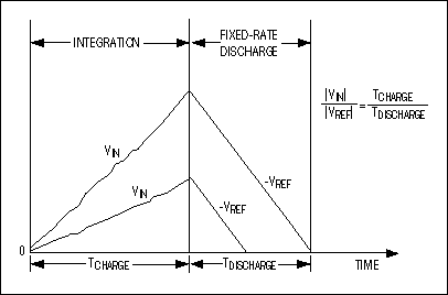
Note that even the clock frequency does not have to have high stability, because both ramp-up and ramp down time are
measured with the same clock.If the clock slows down 10%, the initial ramp will go 10% higher than normal, requiring
10% longer ramp down time resulting in the same final count.
Only the discharge current produced by precise Vref has to be of high stability.
Integrating ADCs are extremely slow devices with low input bandwidths. But their ability to
reject high-frequency noise and fixed low frequencies such as 50Hz or 60Hz makes them useful in noisy
industrial environments and applications . Provide 10-18 bit resolution. A conversion time for a medium speed
12 bit integrating ADC is about 20mS.
This type of ADC is most commonly used in multi-meters.
Sigma-delta ADCs
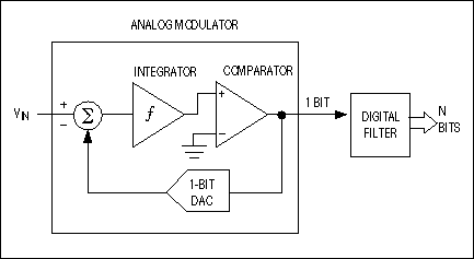
Sigma-delta converters , also called oversampling converters, consist of 2 major blocks: modulator and digital filter .
The modulator, whose architecture is similar to that of a dual-slope ADC, includes an integrator and a comparator with a feedback
loop that contains a 1-bit DAC.
The modulator is oversampling the input signal, transforming it to a serial bit stream with a frequency well above the
required sampling rate. The output filter then converts the bit stream to a sequence of parallel digital words
at the sampling rate. The delta-sigma converters perform high-speed, low resolution (1-bit) A/D conversions, and
then remove the resulting high-level quantization noise by passing the signal through analog and digital filters.
Features: high resolution , high accuracy , low noise, low cost.
Good for applications with a bandwidth up to 1MHz, such as speech, audio.
References:
1.The scientist and engineer's guide to digital signal processing,Second Edition,Prentice Hall
2.Horowitz P.,Hill W., The art of electronics , Second edition,Cambridge
3.Websites: www.analog.com , www.national.com , www.maxim.com , www.intersil.com
|