=My experience of working with high voltage isolation devices=
These short articles are written for the purpose of summarizing knowledge gained during work on different projects.
Alex P. for Hitequest
Many applications such as battery charging and monitoring, sensor signal conditioning,
communication interfaces, etc require galvanic isolation between circuits to prevent
dangerous voltages or currents from one part of the system damaging the other part.
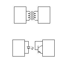
Typically, we use optical or magnetic coupling for isolation.
They can withstand hundreds and thousands volts of DC or AC voltage between domains.
I got to experiment with high voltage when I was involved in integration of galvanic isolation barrier into SOC (system on chip) device.
First of all, there are some standards (European, American or International depending on the market), defining isolation parameters and methods of their validation.
UL1577, VDE 0884, IEC 60950 are among the most popular standards.
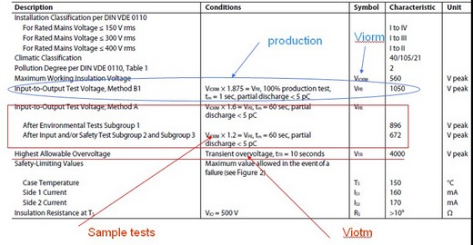
Here is an example of a typical isolator data sheet:
This device, as well as mine, is supposed to work at 560v at maximum working insulation
voltage and occasionally withstand much higher voltages,
such as Viorm = 1050v or Vtr=4000v.
Data sheets have different terms for the same parameters, so I listed below the most
common ones:
Viorm is max working isolation voltage including pick value of repetitive voltages, 560v for this example
Viowm is max working isolation voltage long term (for DC Viorm = Viowm, otherwise depends on manufacturer spec)
Viotm or Vtr is max transient overvoltage pulse value, 4000v for this example
Viso is max RMS or DC withstanding isolation voltage for 1 min
Viosm is surge isolation voltage, max instantaneous pulse of short time, (Viosm=Viotm=?)
How to validate the quality of insulation? The quick and dirty method would be to
increment the voltage until the barrier brakes.
That would give an idea of the limits of insulation.
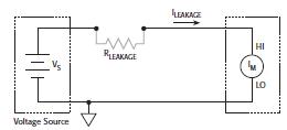
High voltage leakage current
According to UL 1577, each isolator shall be capable of withstanding without breakdown for 60 seconds a potential, equal to the rated dielectric insulation voltage, applied between the input and output terminals. The voltage can be DC or AC rms 40-70 Hz sinusoidal waveform. Instead of 60 seconds the standard allows 1 second under 120 percent of the rated dielectric insulation voltage. In our example the rated voltage is 560v.
The pass or fail criteria is determined on the measured leakage current.
Ideally, the leakage current through insulation barrier should be very low – in range of picoamperes or less. Devices with higher leakage current values may give early warning about potential insulation quality problem.
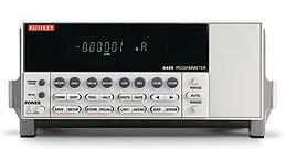
I used Keithley picoammeter model 6517B because it has built-in 1000v source.
Low current measurements, below 1uA, are usually affected by noise, leakage, electromagnetic interferences.
Guarding and shielding are used to minimize these problems.
Guarding involves an extra conductor, driven at the same potential as the current
sensitive path and physically surrounding the sensitive conductor, reducing parasitic
leakage currents in cables and fixture.
Shielding is used to prevent unwanted noise signals from getting to the input of meter.
Cables and test fixture should both be shielded for best results.
Safety
Don't use anti-static wrist bands while working with voltages over 40v
Add interlock to the fixture allowing voltage only when cover is closed
Double insulate all electrical connections
Put rubber mats on the floor in the working area
Place high voltage warning signs around working area
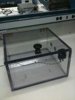
Initially we built the enclosure from insulating material (transparent plastic) for safety purpose. It is shown on diag1 with interlock switch under the cover.
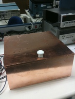
Later we modified it to add copper foil shielding see diag2.
Partial discharge Another approach to validate isolation is called Partial discharge testing, described in VDE 0884, IEC 60950.
Partial discharge happens due to the presence of so called microvoids in insulation
which can be air pockets or contamination.
Voltage stress causes corona discharge in microvoids, but as localized electrical
discharge it only partially bridges the insulation.
Discharges in microvoids cause insulation erosion, eventually resulting in future
breakdown of the insulation.
Lab equipment for partial discharge measurements:
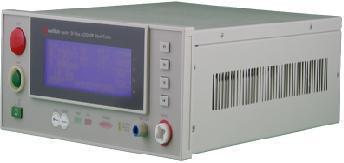
HiPot tester Sentry-30 from QuadTech.
It can source 0-5kV AC voltage, 0-6kV DC voltage with maximum current 20mA.
Also measure R up to 50GOhm. It has GPIB or RS-232 interface.
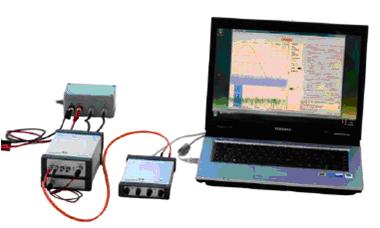
MPD 600 partial discharge measuring system from Omicron.
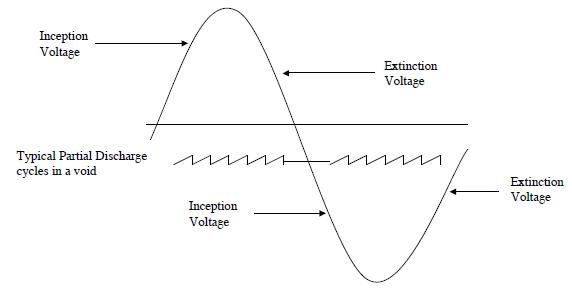
As sine wave high voltage is applied to the barrier, the localized ionization on voids
starts at one voltage and stops at lower voltage.
These are called the inception and extinction voltages.
Partial discharges appear as pulses of short duration (see diagram below).
Typically, manufacturers use 5pC limit for partial discharge as you can see in the spec
example above.
How much is 5pC?
Knowing that
Q = C x V,
If V = 1000v, C = 5pC/1000v = 5fF is the capacitance of void structure.
In terms of current spike that the charge may result in will be 5nA over 1mS:
I = Q/t = 5pC/1mS = 5nA
In this context, the partial discharge test limit of 5pC represents a very relaxed
pass level criteria. If 5pC discharges did actually occur in such a small insulation
structure, it would, in all probability, be rapidly followed by avalanche break down.