|
Scan
Scan is a design technique used in IC manufacturing to increase the overall testability
of a circuit.
Scan tests are generated by ATPG tools - Automatic Test Pattern Generation.
Unlike the functional tests that check chip functionality, scan tests cover stuck-at-faults,
caused by manufacturing problems.
Physical manufacturing defects, such as
- silicon defects
- photo lithography defects
- mask contamination
- process variation
- defective oxide
cause electrical defects, such as
- shorts (bridging faults)
- opens
- transistor stuck on open
- changes in threshold voltage
that in their turn cause logical defects, such as
- logic stuck at 1/0
- slower transition (delay fault)
- AND-bridging,OR-bridging
Below is an example of stuck-at-false.
You can see how a contamination on a wafer is causing a resistive "short" of a transistor,
resulting in a stuck-at-zero failure of the gate.
How the scan works
Basically, all FFs in the design are replaced with scan type FFs. It makes all FFs in the design controllable
and observable by chaining them together and shifting test data in and out.
Scan type FF contains a MUX to select either a normal mode data D or a scan data SI.
SE is a control input.
The first step is to put a circuit into a scan mode.
The whole chip is divided into parts (scan chains).
Serial data is applied to the input of every chain and getting shifted between FFs to the outputs.
Every scan chain output is tested for the proper data coming out.
The nice part is that ATPG tool does all FF replacements automatically based on design_setup file
prepared by designer.
Scan insertion usually adds 15%-30% of area per FF.
IDDQ
IDDQ - is another test technique used in IC manufacturing.
It covers manufacturing defects,such as bridging faults.
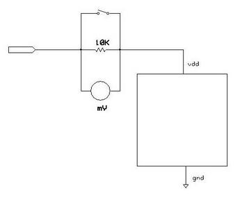
The idea of this test is to measure drain current through the chip, while it is in the static state.
Normally a CMOS logic consumes very little current in a static state.
If there are any internal shorts then higher Icc current should indicate this.
The Iddq test takes relatively long
time since many static states must be covered. IDDQ test does not cover timing problems.
The diagram below illustrates the idea of performing low Iddq current measurements. It is self explanatory.
References:
1.John F. Wakerly Digital design,principles and practices,Second Edition,Prentice Hall,1994
2.Alfred Crouch Design-for-Test for digital ICs and embedded core systems,Prentice Hall,1999
3.Abramovici, Digital system testing and testable design,Computer science press,1990
|