Q:
how to design a divide-by-3 counter with 50% duty cycle?
Here is a possible solution...
Start with the timing diagram. It shows an input clock, an output of a regular divide-by-3 counter
and an output of divide-by-3 counter with 50% duty cycle.
It is obvious from the diagram, that we have to use both rising and falling edges
of the input clock.
The next drawing is a state diagram.
On this diagram R - is a rising edge of input clock, and F - is a falling edge.
How many FF do we need to implement 6 states? At least 3. In this example I am going to use 4 D-type FF just to simplify
the design.
Now, look at the table below. Q0 ... Q3 are the outputs of FFs. Q - is the output of the devider
with 50% duty cycle. In the first raw the outputs are in the initial state: 0000. In the second raw - the data after
the first rising edge and so on.The status of the FFs' ouputs is changing on every rising or falling edge of the input clock
according to the information on D-inputs. So, D-inputs should have the data before the clock edge.
in_clk
Q
Q0
Q1
Q2
Q3
D0
D1
D2
D3
Reset
0
0
0
0
0
1
0
0
0
R1
1
1
0
0
0
1
1
0
0
F1
1
1
1
0
0
0
1
1
0
R2
1
0
1
1
0
0
0
1
1
F2
0
0
0
1
1
0
0
0
1
R3
0
0
0
0
1
0
0
0
0
F3
0
0
0
0
0
1
0
0
0
These equations are resulting from the table analysis:
D1 = Q0
D2 = Q1
D3 = Q2
D0 = (Q1+Q2+Q3)'
Q = Q0Q1'Q2'Q3'+Q0Q1Q2'Q3'+Q0'Q1Q2Q3' = Q1Q3'(Q0Q2'+Q0'Q2)+Q0Q1'Q2'Q3'
Next step will be a circuit diagram:
This design is just for illustration and can be optimized further.
=============================================
Comments from Badri: Hey Guys
Excellent web site. Thanks.
I had one comment on one of your solutions:
In "Electronics Hardware Questions", the question: how to design a
divide-by-3 counter with equal duty cycle ?
I think the suggested solution is unnecessarily complex. My solution is like
this (sorry I don't have a schematic tool)
Make a circular shift register with 3 flops, with initial state = 001 (or
100 or 010). (Circular shift register is a snake swallowing its own tail).
All the 3 flops in this are clocked on the positive edge of the input clock.
Now take any one of the flop outputs from above (call it A), and feed it to
the D input of another flop. This flop is clocked by the inverted version of
the input clock. Call this flop's output A_. Then, "A OR A_" is the required
divided-by-three clock with 50% duty cycle.
We only need 4 flops, one inverter and one OR gate for this.
Thanks
Badri
=============================================
Comments from Satish:
Does the solution for divide by 3 counter by Badri work? I tried it and
it is not working for me.
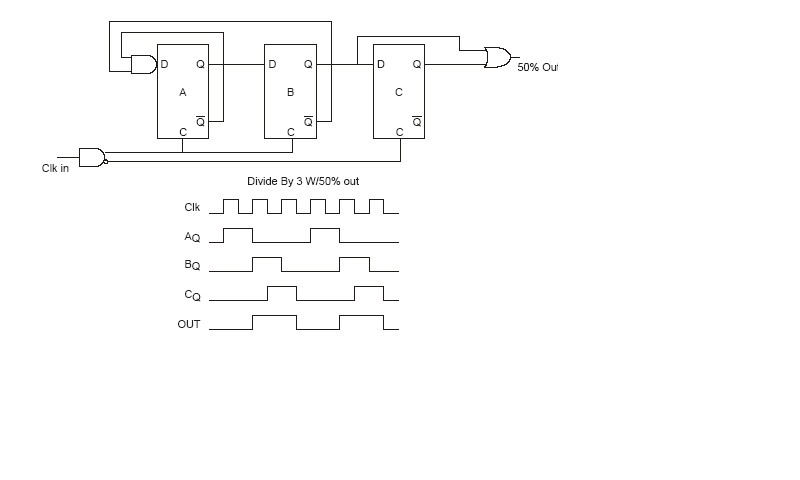
I have attached my solution for divide by-3 circuit which i think is
simple
enough. This is how the circuit works.
We add a gate on the clock to get differential Clock and Clock bar, a
flip flop that triggers on
the Clock Bar rising edge (Clock Neg.) to shift the output of "B" by 90
degrees and a gate to OR the outputs of FF "B" and FF "C" to produce
the 50% output.
I have attached a .jpg file of the schematic
Satish B.
=============================================
Nuno: Hello,
I do have a simpler solution to the question: "how to
design a divide-by-3 counter with equal duty cycle ?" under
section: "Electronics Hardware Questions". It consists of
two D or JK flip-flops (called A & B) with their input's
tied high. clocks are falling edge triggered. Input "clk A"
is connected to "NEG_Q B", Input "clk B" to a XOR output.
One of the XOR inputs is connected to "Q A", witch is also
our main output. Main clock signal goes to the other XOR
input.